Introduce
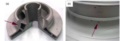
The impeller is the core component of the centrifugal pump. During operation, the impeller must withstand vibration and centrifugal force, thereby exerting tensile, compressive and bending stress on the blade. In addition, flowing through external pinholes or micro-holes (as shown in Figure 1) tends to cause pitting corrosion, thereby reducing
The efficiency of fluid transfer. Therefore, eliminating internal and surface defects of impeller blades is essential to prevent creep, fatigue failure and even damage. Casting flow analysis can be incorporated into the preliminary design process to reduce the possibility of forming defects in investment casting (such as segregation, surface pinholes, shrinkage and porosity), which can significantly improve the quality of castings and shorten the product development process. Several methods have been developed to simulate the pouring process in casting, including the semi-implicit method of pressure correlation equation (SIMPLE), mark and element (MAC) method 2 and the volume of fluid solution algorithm (SOLA-VOF) method. 3 In order to improve the quality of impeller castings, this study uses the mold flow analysis technology in AnyCasting to simulate the pouring process to optimize the pouring system and increase the output and productivity of castings.

1 Typical defects formed by the spiral impeller of a centrifugal pump: internal shrinkage pores; b surface defects
Method
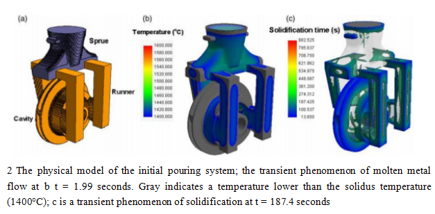
The components used in the experiment included an impeller mold with a diameter of 96.803 mm and a gate of 60 mm with two runners on both sides. Figure 2a illustrates the initial design of the gating system. The material of the pump is 17-4PH stainless steel. The physical properties of stainless steel materials are as follows: density (ρ) is 7750 kg m-3, specific heat (S) is 459.45 J kg-1·°C, liquidus temperature (TP) is 1440°C, and solidus temperature (TS) is 1400°C. The coefficient of thermal expansion and thermal conductivity change significantly with temperature, and they are regarded as variables. For physical parameters (such as density, specific heat and latent heat) that have a limited change with temperature, they are treated with constants in the simulation software. The main purpose of the numerical simulation of the pouring and solidification process is to optimize the process parameters and realize the prediction and control of casting defects. We used SolidWorks 3D software to develop accurate element models of the impeller blades and gating system. Then import the model into AnyCasting for preprocessing based on the finite difference method (FDM). In the discrete calculation node, we derived a difference equation containing a finite number of unknowns. Solving the difference equations produces approximate analytical solutions, which are used in the design of physical parameters and process conditions in numerical simulations. The convergence criterion of the iterative calculation is <0.001. According to the residual melt modulus (RMM)4 and the Niyama criterion model 5,6, the probability of occurrence of defects is evaluated. The filling of molten metal involves non-isothermal flow, with heat transfer losses and solidification. According to the conservation of mass, momentum and energy, various thermodynamic behaviors and flow field evolution can be analyzed. The continuity equation, the Navier-Stokes equation (for momentum), the energy equation and the fluid volume function are used to predict the filling behavior of molten metal and describe the changes in the free surface of the metal flow. The Niyama criterion model for shrinkage prediction is specified as follows6:

Where G represents the local temperature gradient (K m−1) of the region of interest; R is the cooling rate; CNiyama represents the threshold of the Niyama standard. The CNiyama value used here is 1.0 K1/2 s1/2 mm−1.4
Results and discussion
Numerical analysis of initial pouring plan
Figure 2a shows the design of the vertical gating system, which contains 3849925 computing units. The pouring temperature (Tcasting) and shell mold temperature (Tceramic) are 1580 and 1200°C, respectively. The transient flow of molten metal at t = 1.9 seconds is shown in Figure 2b. The pouring was completed in approximately 3.7 seconds. As shown in the picture, the hub was filled with blades before. This is because the blade structure is more complex and the thickness is uneven, which increases the flow resistance and the tendency to generate turbulence. Figure 2c shows the sequence of molten metal solidification. The solidification was completed in approximately 882.5 seconds.The outer edge solidified at about 187 seconds, which happened earlier than the blade. Figure 3 shows the probability of defects in each part of the casting based on the initial casting parameters using the Niyama criterion model (that is, considering the ratio of temperature gradient and cooling rate) combined with RMM. RMM represents the volume of the retained melt divided by the surface area when the critical solids fraction is reached at each grid. The lower the value of RMM, the greater the possibility of forming defects. As shown in the figure, shrinkage defects are prone to appear in thin-walled areas and areas with large changes. The thickness of the structural wall. We speculate that the use of molten metal with a lower temperature and a lower shell mold temperature causes the structure near the thin wall to cool faster, resulting in internal residual stress and surface shrinkage and deformation. In addition, the rapid cooling of the feed channel between the secondary dendrites increases the flow resistance of the molten metal, resulting in insufficient feed and eventually shrinkage.


